| Home | AmMin | GMR | RiMG | Collectors Corner | Directory | Short Courses | |
|
|
|||||||

|
|
Volume 63, pages 219-229,
1978
The origins of color in minerals KURT NASSAU Bell Laboratories Murray Hill, New Jersey 07974 Abstract Four formalisms are outlined. Crystal field theory explains the color as well as the fluorescence in transition-metal-containing minerals such as azurite and ruby. The trap concept, as part of crystal field theory, explains the varying stability of electron and hole color centers with respect to light or heat bleaching, as well as phenomena such as thermoluminescence. The molecular orbital formalism explains the color of charge transfer minerals such as blue sapphire and crocoite involving metals, as well as the nonmetal-involving colors in lazurite, graphite and organically colored minerals. Band theory explains the colors of metallic minerals; the color range black-red-orange-yellow-colorless in minerals such as galena, proustite, greenockite, diamond, as well as the impurity-caused yellow and blue colors in diamond. Lastly, there are the well-known pseudochromatic colors explained by physical optics involving dispersion, scattering, interference, and diffraction Introduction Four distinct physical theories (formalisms) are required for complete coverage in the processes by which intrinsic constituents, impurities, defects, and specific structures produce the visual effects we designate as color. All four are necessary in that each provides insights which the others do not when applied to specific situations. An outline with examples is given in Table 1.This classification goes well beyond the traditional idiochromatic ("self-colored," as from a major ingredient), allochromatic ("other-colored," as from an impurity), and pseudochromatic ("false colored" as originating from physical optical effects), although these three are, in fact, indirectly included in several places in Table 1. The current approaches transcend the conventional wisdom which attempts to attribute blue-green colors to copper, deep blue to cobalt, red or green to chromium, and so on. To give only one example: deep blue colors may be produced by idiochromatic copper (shattuckite), allochromatic cobalt (blue spinel), by a color center (Maxixe-type irradiated beryl), by charge transfer between iron and titanium (blue sapphire), by molecular orbital effects in S-3 units (lapis lazuli), by boron acceptors in a band gap (blue diamond), and by pseudochromatic light interference (blue regions in opal). The approach here used is tutorial in nature and references are given for further reading or, in some instances, for specific examples. Color illustrations of some of the principles involved have been published in an earlier less technical version (Nassau, 1975a) Specific examples are given where the cause of the color is reasonably well established, although reinterpretations continue to appear even in materials, such as smoky quartz (Nassau, 1975b), which have been extensively investigated over many years.Specific causes for color in the majority of minerals are in fact not known, and detailed investigations, often requiring precision spectroscopy, impurity analysis down to ppm levels, magnetic resonance, and sometimes radiation and even laboratory synthetic procedures, may be necessary for unambiguous conclusions. As an example, the deep blue of diamonds such as the "Hope" almost certainly originates in merely a few boron atoms per million of carbon atoms (this also provides the electrical conductivity). Previously the blue color had been attributed to aluminum present at much higher concentration, but synthesis demonstrates that aluminum in this instance does not produce a blue color, whereas boron does (Chrenko, 1973). Many different systems of designation are used for the energy of quantized systems (e.g. energy
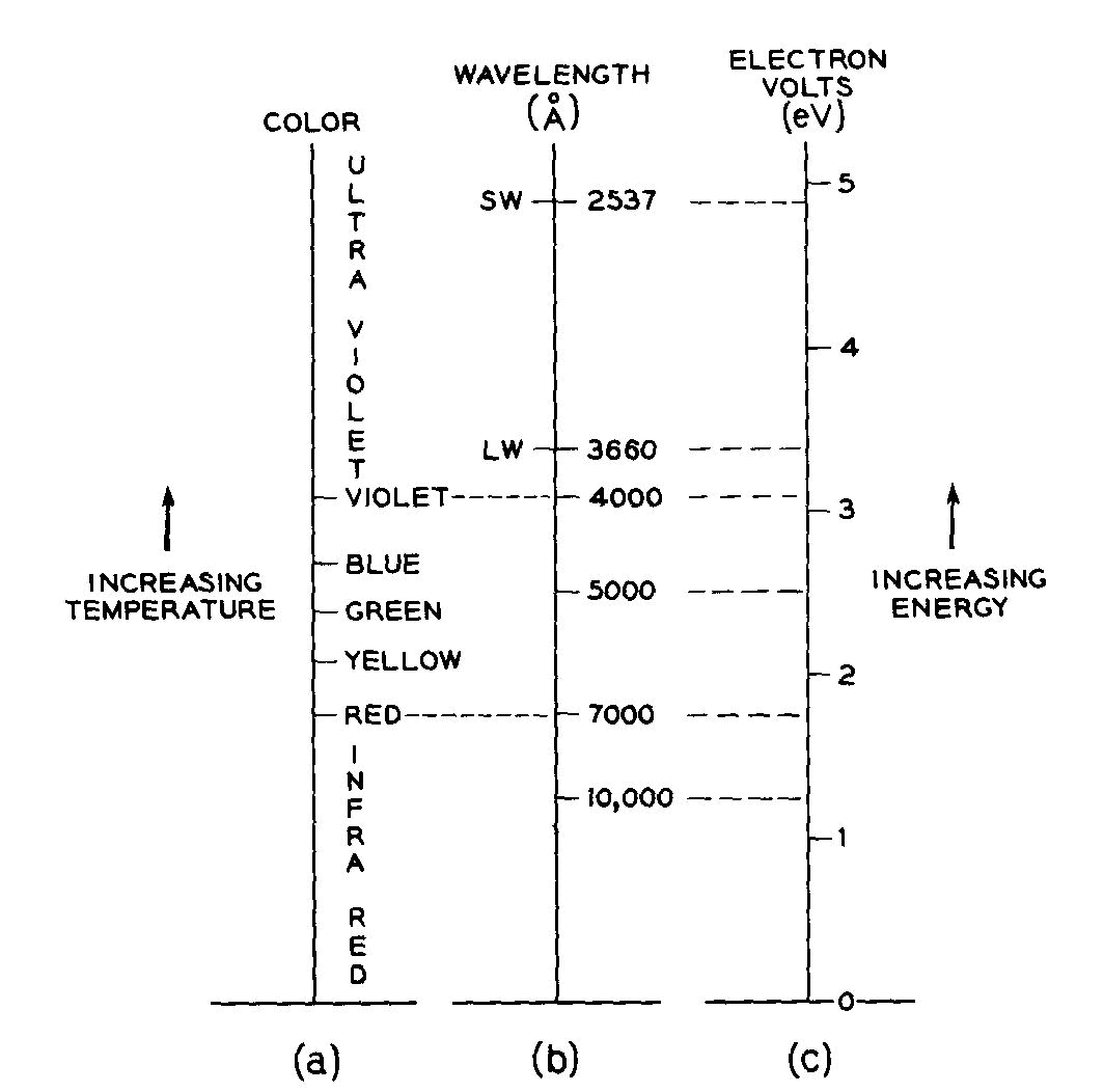
as wave numbers in cm-1, electron volts eV, kcal/mole, etc.;
or the equivalent light wavelength in nm, mm, or A, or
its frequency in sec-1 or Hertz, Hz). The eV scale used in this article and its relationship to the spectrally pure
colors is illustrated in Figure 1.
Table 1. Twelve types of color in minerals
The crystal field formalism Color best explained by the crystal field formalism involves predominantly ionic crystals containing ions with unpaired electrons. These usually originate in elements with partially filled d shells such as V, Cr, Mn, Fe, Co, Ni, and Cu, or in elements with partially filled f shells such as the actinides and lanthanides.There are no unpaired electrons when all electron shells are completely full or empty as in Cr6+, Ce4+, or Cu+, when this type of color cannot result. Of these transition elements, Fe is the most plentiful (about 5% of the earth's crust) and is therefore the dominant color contributor in minerals. Consider now a mineral containing, say, some trivalent chromium. The electronic configuration of
Cr3+
is 1s22s22p63s23p63d3; here only the three unpaired electrons in the 3d shell can interact with visible light so as to
produce absorption and color. Due to the quantization of energy, a system such as Cr3+ can exist only in a limited
number of states, the "energy levels." These energy levels can be shown on a diagram such as Figure 2, by
their energy content with respect to the "ground state," i.e. the state of the ion when it is not interacting
with any kind of radiation and is in its lowest energy state.
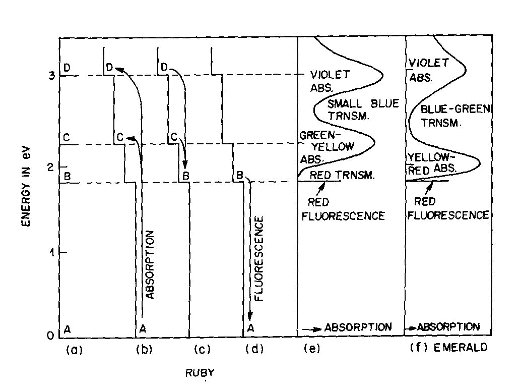
Fig. 2. Energy levels, transitions, and color absorptions in ruby (a) to (e) and in emerald (f). The actual calculation of such energy levels is quite complex and, for a given atom, has to include the following parameters: the valence state, the symmetry of the ion's environment (i.e. the coordination polyhedron of charges which produces the "crystal field," also sometimes called the "ligand field") including any distortions from ideal tetrahedral, octahedral, etc.; and the strength of the crystal field, i.e. the nature and strength of the bonding. The result of such a calculation is an energy level scheme such as that of ruby, (about 1 % Cr3+ substituted for A13+ in the distorted octahedral sites of A12O3 with very strong bonding resulting in an Al-O distance of 1.91 A) shown in Figure 2a. The crystal field calculation not only gives the excited energy levels (only the first three are shown in Figure 2a) with respect to the ground state A, but also a set of "selection rules," covering the probability of parallel electron paths. For example, excitation (light absorption) can result in this instance in a change from the ground state A to states C and D with high probability, but the change from A to B is relatively forbidden (Fig. 2b). Deexcitation cannot occur from D or C back to A but must first pass through state B with the emission of heat to the lattice as in Figure 2c; this can now be followed by light emission, the red fluorescence of ruby, from level B back to the ground state A as in Figure 2d.Additional complications not so far mentioned include temperature and other broadening of energy levels and the fact that, since the crystal field can differ with orientation in an anisotropic crystal, so can the energy level scheme, resulting in pleochroism (dichroism in the case of ruby). The actual unpolarized absorption spectrum of ruby shown in Figure 2e illustrates how the broadened absorbing D and C levels produce violet and green-yellow absorption bands. The remaining light transmission produces the strong red color of ruby with its blue (purple) cast. Some of the energy absorbed into the C and D absorption bands (as well as into other absorption bands at higher energies in the ultraviolet not shown) reappears as red fluorescence from energy level B (which remains quite narrow), thus adding to the red glow of this gemstone. It can be seen to be a coincidence that both the color as well as the fluorescence of ruby is red. It should be noted that the presence of Fe impurity can completely "quench" the fluorescence by siphoning off energy from the fluorescence level B without significantly affecting the absorption caused color. The effect of a change in the strength of the crystal field is well illustrated by comparing ruby to emerald, in which
Cr3+ also substitutes for
A13+. The
distorted six-coordinated site and Al-O distances in emerald are similar to those in ruby, but the effect of the added
Be and Si and the change in structure from the hexagonal close-packed oxygen framework of Al2O3 to the more open
structure of Be3A12Si6O18 leads to metal-oxygen bonds of higher covalency than in ruby, a lower electron density on the
oxygens, and accordingly produces a crystal field of reduced strength. The resulting relatively small shifts of the C
and D absorption bands in Figure 2f essentially eliminate the red transmission but intensify the blue-green
transmission, leading to the characteristic emerald color. The fluorescence level B is almost unchanged, and here again
the strong red fluorescence adds to the quality of the gemstone color when not quenched by iron impurities. A similar
change in crystal field results in a change from red to green as the concentration of Cr2O3 in
A12O3 is increased,
resulting in a less ionic bonding and a reduced crystal field.
Alexandrite (Cr A last complication of crystal-field-caused color is that the same ion may enter several different
sites in a mineral, thus providing several sets of energy level schemes and resulting in superimposed absorption bands.
If there is transfer of electrons among different sites, then the molecular orbital formalism described below can
produce additional absorptions.
Detailed treatments of crystal field concepts have been given by Burns (1970) and Wood (1969), and
may also be found in recent inorganic texts such as that of Cotton and Wilkinson (1972). Intermediate treatments by
Loeffler and Burns (1976), Frye (1974), and Fyfe (1964) can be recommended.
The crystal field formalism is appropriate for three types of color: those caused by transition
metals either as a major ingredient or as an impurity, and that produced by color centers.
Idiochromatic colors caused by major
transition-metal constituents Allochromatic colors caused by transition-metal impurities
Some well-established examples of impurity caused color are given in Table 3. The touchstones of this
type of color are the nature of the streak, which usually represents the color of the pure compound, and the occurrence
of such a mineral in various colors; it is usually safe to assume that the lightest color represents the pure mineral.
The cause of color cannot necessarily be ascribed to an impurity just because the impurity is known to be present in a
significant amount. Other impurities at a lower concentration may be involved, or a color center may As discussed above, the same impurity can cause widely different colors, such as Cr-caused ruby red and emerald green. However, there are some emeralds which derive their color either partially or totally from vanadium (Wood and Nassau, 1968).
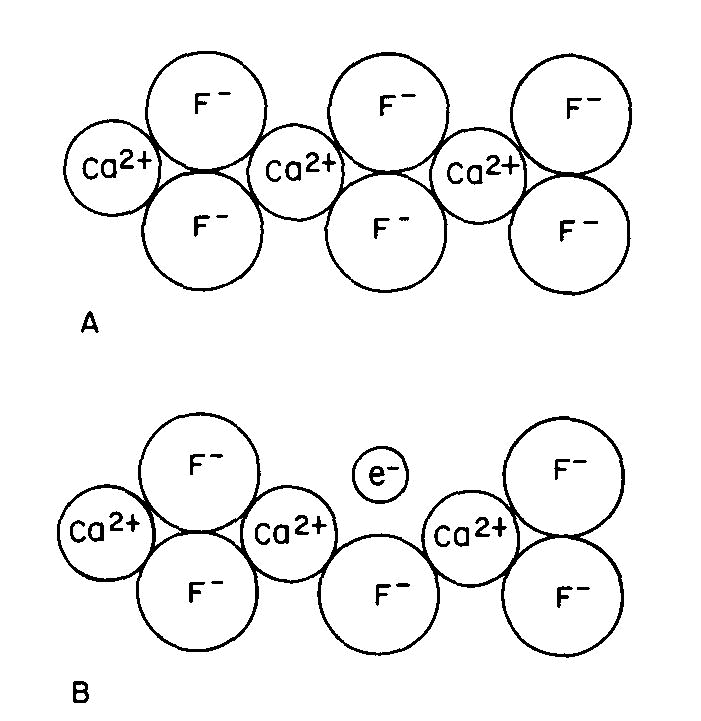
Many color centers are known, but the exact color causing mechanism has been established in only a very few instances. One of these is the purple "F center" or Frenkel defect of fluorite, one of many types of color center which can form in fluorite. Figure 3A is a two-dimensional representation of the CaF2 structure. There are several ways by which an F- ion can be missing from its usual position: this can occur during growth or when energetic radiation displaces an F- ion from its usual position to another point in the crystal; we can also create such centers by growing fluorite in the presence of excess Ca, or by removing some F from a crystal by the application of an electric field.
Fig 3. Fluorite structure (schematic): (A) normal, (B) containing an "F-center" where a fluorine ion has been replaced by an electron. Since the crystal must remain electrically neutral, an electron usually occupies the empty position to produce the F-center or "electron color center" as shown in Figure 3B. This unpaired electron can now exist in excited states, the energy of which is controlled by the same crystal field factors described previously; color and fluorescence can now occur by the same types of transitions as described above.
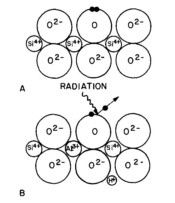
Fig. 4. Quartz structure (schematic): (A) normal, (B) containing Al3+ substituted for Si4+ with an H+ for charge neutrality. Radiation ejects one of a pair of electrons from an O2- and leaves a "hole" color center of smoky quartz. In the case of smoky quartz, there is a "hole color center." A necessary precursor to this color center is the presence in the quartz (Fig. 4A) of impurity Al3+ substituting for Si4+ ions with some alkali (e.g. Na+) or a hydrogen ion (H+) nearby to maintain electroneutrality (Fig. 4B). Interstitial Al does not serve as a precursor to form smoky quartz. Most natural quartz contains substitutional Al at the several hundred ppm
Cerium: Parisite (yellow)
Chromium :
Emerald, grossularite, hiddenite, Cr-jade, Cr-tourmaline (green); alexandrite (green-red); ruby, spinel, topaz (red) The electron displaced in the process depicted in Figure 4B becomes "trapped" somewhere else in the quartz crystal without causing any additional light absorption. If the smoky quartz is now heated (say to 400°C-see Nassau and Prescott, 1977) these displaced electrons can be released from their traps and return to the hole center; all electrons are again paired and the quartz returns to colorless. The bleaching temperature is thus not a characteristic of the color center itself and often varies. On re-irradiation the color can once again be restored. Amethyst is a similar color center, involving Fe instead of Al. Depending on the location and environment of the Fe the color obtained on heating amethyst is either yellow (citrine as in most amethyst) or green (the "greened amethyst" from Montezuman, Rio Prado, Brazil; Rose and Lietz, 1954). Even though the yellow or green color after heating is an allochromatic transition-metal impurity color, the amethyst color itself derives from a color center. Irradiation after heating can recreate the color center and the amethyst color. Table 4. Color centers Essentially
stable to light:
Amethyst, fluorite (purple); smoky quartz (brown to black); irradiated diamond (green, yellow, brown, black, blue,
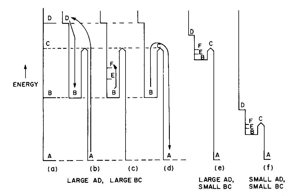
pink); some natural and irradiated topaz (blue) These and other color centers are listed in Table 4. Note that irradiation with energy as low as ultraviolet light can produce color centers, and that some of these colors are not stable to light exposure. These phenomena can be described on energy level diagrams as shown in Figure 5, using the trap concept. The diagram of Figure 5a could be that of smoky quartz. Starting with colorless quartz (containing the substitutional Al precursor) in the ground state A, radiation is absorbed with the system moving into the excited state D. Due to a selection rule the system must move to state B, as shown in Figure 5b, before it can return to the ground state.
Fig. 5. Energy-level schemes showing "traps" involved in phosphorescence, thermolumincescence, and bleaching color centers. State B, the color center, is a "trapped" state with an energy barrier from B to C which must be surmounted before the color center can disappear. While in State B light can be absorbed into other excited levels such as E and F (Fig. 5c), and cause the smoky color. This color will remain until enough energy is supplied (e.g. by heating to 400°C) to permit the system to overcome the barrier and return to the ground state, as in Figure 5d. The ground state is colorless because the transition to the lowest absorbing excited level D requires a larger energy than that present in visible light. In case of a hole color center, the trap is not physically located at the center (see below); the energy diagram, applying to the hole-trap complex,, is the same as that for an electron color center. In the energy level scheme of Figures 5a to 5d, the energy of formation of the color center (A to D) is large and the energy for its destruction or "bleaching" (B to C) is also relatively large. The light-stable color centers of Table 4 are of this type. The scheme of Figure 5e illustrates a system with a large formation energy but a small bleaching energy. Since B to C is here within the range of energies present in visible light, the system will bleach by light energy induced leakage over the barrier C at the same time that color is observed from absorption into E and F. This state of affairs applies to most of the light-bleaching color centers listed in Table 4. For example, Maxixe-type deep blue irradiated beryl (Nassau et al., 1976) and brown irradiated topaz will both fade after some days exposure to light or on heating for a short period to 100 or 200°C. When kept in the dark, the color will persist over many years (more than 60 years in the case of Maxixe beryl; Nassau et al., 1976). If both formation and bleaching energies are low, the diagram of Figure 5f applies, for example, to photochromic hackmanite. In this colorless material even ultraviolet light with energy less than 5eV (note that gamma rays range up to over 1 million eV) is sufficient to be absorbed via level D and produces a red color center (B, E, F) which bleaches rapidly on exposure to light.Phosphorescence involves an even smaller bleaching energy B to C than that necessary for light bleaching. This occurs when the return to the ground state involves the emission of light of energy corresponding to the C to A return to the ground state and when the'-thermal excitations present at room temperature are sufficient to carry the system slowly over the barrier at C. Phosphorescence is shown by some fluorite, calcite, diamond, etc. Fluorescence and phosphorescence "lifetimes" grade into each other; rapid phosphorescence with a very small barrier may seem to be merely fluorescence. If the trap BC is a little deeper, thermoluminescence can result; the fluorescence occurs at a fairly well defined temperature on heating, when the thermal excitation permits rapid leakage out of the trap. Phosphorescence and thermoluminescence are not confined to color centers (any more than fluorescence is), but the energy level schemes can nevertheless be represented as in Figure 5 wherever such phenomena occur. The bleaching process in the case of a hole center involves the release of electrons trapped elsewhere in the crystal. Since these electrons may be trapped at various sites, there may be a broad bleaching range in a crystal and also different bleaching temperatures in different specimens as was, in fact, observed in a series of smoky quartz specimens (Nassau and Prescott, 1977). This implies a variation in the barrier height C, although the color center itself (13, E, F in Fig. 5) remains the same. The touchstone for a color center is bleaching by light or heat and reformation of the color on irradiation. This is not foolproof, however (compare the blue to green change in beryl discussed in the final section), and years of investigations employing optical spectroscopy, paramagnetic resonance, and other techniques have been required to characterize fully the few color centers which are well understood. The molecular orbital formalism This applies to several different types of situations where electrons are involved which are not simply located on single atoms or ions as in the crystal field formalism, but must be considered to be present in multicentered orbits. The results vary depending on whether metal-metal, metal-nonmetal, or nonmetal-nonmetal centers are involved. In the latter two cases the type of bonding is usually predominantly covalent. The result of a molecular orbital treatment is similar to that of a crystal field treatment; both formalisms result in a set of energy levels and associated transition probabilities. Some examples are summarized in Table 5. An introduction to molecular orbital theory has been given by Ballhausen and Gray (1964); charge transfer has been reviewed by Robin and Day (1970) and organic color by Mason (1970).
Similar remarks apply to vanadinite, wulfenite, and scheelite. The last is not colored when pure,
since the charge transfer absorption is not in the visible, but the bright fluorescence of scheelite derives from an
excited molecular orbital state of the charge transfer O -> W in the WO As in crystal field calculations, the point symmetry and geometric distortions of the molecular group
and the strength of bonding are important parameters. Charge transfer transitions usually have high transition
probabilities, thus giving intense colors, and tend to dominate crystal field transition colors when both are present,
although they may also occur in the ultraviolet part of the spectrum.
Charge transfer is also present in the chalcogenides such as pyrite, with S- metal electron
displacement. The optical properties of these types of minerals are, however, best understood using the band formalism
discussed below.
Table 5.
Colors caused by molecular orbital transitions
A. Metal-metal charge transfer: In graphite there are sheets of connected six-membered rings of carbon atoms, and the "r-electrons" can move more or less freely along these sheets. The result is strong light absorption, specular reflection, and anisotropic electrical conductivity, somewhat similar to that in metals, as discussed below. Lastly, there are a number of mineral substances which owe their color to organic pigments, many of biological origin. Some of these are listed in Table 5 and here color, once again, originates in molecular orbital type of transitions within covalently-bonded molecular units.The band theory formalism The crystal field and molecular orbital theories apply to electrons located on ions, at defects, and on groups of atoms. Band theory treats electrons as belonging to the crystal as a whole and applies to a wide range of materials, as indicated in Table 6. General accounts of band theory can be found in solid-state physics texts such as that by Kittel (1976).
The band theory of metals
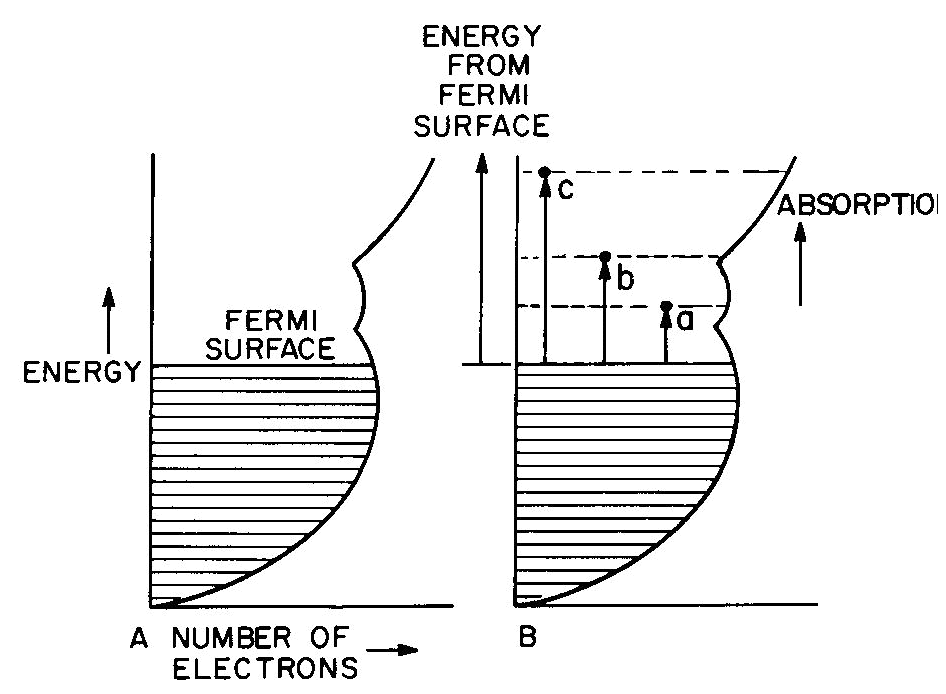
Fig. 6. Band diagram of a typical metal (A) showing light
absorption transitions in (B).
Band theory and semiconductors
Table 6. Band theory colors
Conductors (metallic color and luster)
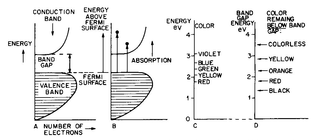
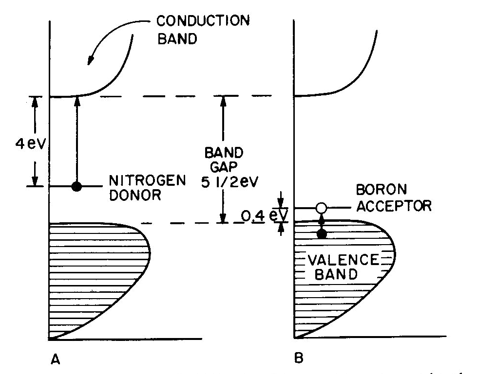
Fig. 7. Band diagrams of a typical semiconductor (A), showing light absorption transmissions (B); the dependence of color on the energy of light in (C) leads to the color remaining for various band gap energies in (D). Light absorption occurs as in Figure 7B, with absorption possible at all energies above the band-gap energy Eg, but not below. Because of limitations associated with the band-gap, the luster is not usually metallic except at very small values of Eg. If the band gap is smaller than the visible-light range (Fig. 7C), then all light energies can be absorbed and a dark gray or black color results, as in galena with Eg less than 0.4eV. Such "narrow band-gap semiconductor" materials provide rectifying and amplifying characteristics in suitable geometries (silicon and germanium diodes, transistors, solar cells; note that galena crystals served as point contact rectifiers in the early "crystal" radio sets). Minerals such as pyrite can also be treated as narrow-band-gap materials (Pridmore and Shuey, 1976). If a narrow-band-gap semiconductor is heated to a high enough temperature so that thermal excitation can bridge the band-gap, then the electrons excited into the conduction band will cause the material to behave as a metal. At the other extreme, "large-band-gap semiconductors" with Eg larger than the range of visible light will not be able to absorb in the visible and will thus be colorless, as in pure diamond and sphalerite with Eg about 5 1/2 eV and 3 1/2 eV respectively. With an intermediate band-gap of about 2eV, as in proustite, only red light is transmitted; all other colors have energies larger than Eg and therefore are absorbed, as in Figures 7C and 7D. With a band-gap of about 2.5eV, as in greenockite, only blue and violet in Figure 7C are absorbed and the resulting color in Figure 7D is yellow. The overall sequence of band gap colors is thus black/red/orange/yellow/colorless. When mixed crystals of CdS (yellow, Eg =2.5eV) and CdSe (black, Eg = 1.6eV) are prepared, the intermediate orange and red colors are indeed obtained (Fig. 12 in color in Nassau, 1975a). Some band-gap semiconductor minerals are listed in Table 6. Semiconducting ore minerals are the subject of a book by Shuey (1975). Impurities in semiconductors Medium- and large-band-gap semiconductors do not conduct electricity at room temperature when pure, since the ambient excitation is insufficient to bridge the band-gap. The presence of certain impurities can affect both the conductivity as well as the light absorption. Consider nitrogen impurity atoms substituting for carbons in a diamond crystal (Eg about 5 1 /2 eV). Since N has one more electron than C, each nitrogen donates one extra electron above the Fermi surface and these "donor" electrons form an impurity level within the band-gap, as shown in Figure 8A. The nitrogen impurity level is still 4eV below the conduction band (a "deep" donor) and is, in fact, somewhat broad. It can only absorb a little violet at 3eV, thus giving a yellow color. A typical deep-yellow diamond may contain one nitrogen atom for every 100,000 carbon atoms. The reduction in the bandgap is insufficient to permit electrical conductivity at room temperature.
Fig. 8. Band diagrams for (A) yellow N-containing diamond and (B) blue B-containing diamond. Boron, having one electron less than carbon, acts in a similar way to produce "acceptor levels" in the band-gap. These are "hole" levels which can accept electrons from the valence band and are located only 0.4eV above the top of the valence band, as shown in Figure 8B. Here again the impurity band is not just a single level, but has a complex structure. resulting in a blue color. A1, which also has one less electron than C and is present in significant amounts in some blue diamonds, had been previously thought to provide the acceptor; however, laboratory synthesis showed that B additions gave blue and that A1 did not (Chrenko, 1973). Since the boron acceptor level is "shallow," ambient thermal excitation can raise electrons from the valence band into the acceptor level, and the resulting holes in the valence band can then conduct electricity. Type IIB blue conducting diamonds such as the "Hope" contain typically one boron atom per million carbon atoms.Blue irradiated diamonds do not conduct electricity, thus providing one distinction between the boron acceptor and the irradiation-produced blue color center in diamond. Gemological testing (Liddicoat, 1977) is required to distinguish between nitrogen donor yellow diamond and irradiated yellow diamond. Color caused by physical optics effects Electrons are not involved in the last four types of colors summarized in Table 7. These effects are well covered in optical mineralogy and optics texts and an extended discussion is therefore not appropriate.With respect to scattering, it may be noted that the luster in pearl originates in overlapping platelets of aragonite. The terminology used for adularescence, aventurescence, schiller, etc. is very confused. The effect observed in moonstone orthoclase and also in some albite (a "floating" white or bluish shimmer) is usually attributed to a layer structure. Light scattered from colloidal particles can produce a very similar effect, as in unhomogenized milk or in some moonstone imitations made by heat-treating synthetic spinel (presumably to precipitate a second phase). It is therefore possible that the bluish moonstone effect is caused by light scattering from very fine particles. The effect is sometimes termed opalescence and is also seen in the white to bluish body color of some opal; it is unrelated to the fire in opal. One other distinction may need emphasis. The colors deriving from interference in a thin film, as in the tarnish film on bornite, is the well-known sequence black/gray/bluegray/white/yellow/orange/red (end of the first order)/violet/blue/green/etc. These colors become washed out along the sequence and are not pure spectral colors. The exact color depends only on the film thickness, the refractive index of the film, and the nature of the incident light.In the case of diffraction there is also interference of light waves, but from a regular diffraction grating as in opal. In this case the colors are spectrally pure and depend only on the grating spacing and the angle of observation. A given region of an opal can diffract only a limited range of colors. For example, for a flat slab of opal with face-centered cubic sphere packing with a spacing of 3A, the color range is green to red; with 2.5A blue to yellow, and with 2A violet to bluegreen. A detailed description of opal has been given by Sanders (1968) and labradorite is discussed by Bolton et al. (1966). Concluding remarks The effect of irradiation and heat on the color of minerals well illustrates the danger of rash conclusions concerning the origins of these colors. Usually irradiation produces electron or hole color centers, while heating permits the trapped electrons and holes to recombine again. The process is reversible and heat-bleached amethyst can usually be recolored by irradiation. An apparently similar change, the converting of golden or green beryl to blue aquamarine on heating can also be reversed by irradiation. Nevertheless, in this case a color center is not involved, but merely a valence change which eliminates a yellow-producing Fe3+ absorption at the violet end of the spectrum on heating; the resulting Fe2+ does not absorb in the visible and the original color can be restored by irradiation (Wood and Nassau, 1968). In the case of pink tourmaline both an electron color center as well as a hole color center have been proposed, but an examination of a large number of specimens by irradiation and heating indicated the occurrence of at least seven differently-behaving pinks (Nassau, 1975c). Clearly, much caution must be used in explaining specific colors.
Color Based on Dispersion: Acknowledgments Helpful discussions with D. L. Wood and M. B. Robbins of the Bell Labs and B. M. Loeffler of Massachusetts Institute of Technology are gratefully acknowledged.
Ballhausen, C. J. and H. B. Gray (1964) Molecular Orbital Theory. Benjamin, New York. Bolton, H. C., L. A. Bursill, A. C. McLaren and R. G. Turne (1966) On the origin of the color in labradorite. Phys. Stat Solidi, 18, 221-230.
Burns, R. G. (1970) Mineralogical Applications of Crystal Field Theory. Cambridge University Press, Cambridge, England. Chrenko, R. M. (1973) Boron, the dominant acceptor in semi conducting diamond. Phys. Rev., B7, 4560-4567. Cotton, F. A., J. B. Harman and R. M. Hedges (1976) Calculations of the ground state electronic structures and electronic spectra of di- and trisulfide radical anions by the scattered wave-SCF-Xa method. J. Am. Chem. Soc., 98, 1417-1427. ______ and G. Wilkinson (1972) Advanced Inorganic Chemistry 3rd ed. Interscience, New York. Frye, K. (1974) Modern Mineralogy. Prentice Hall, New York. Fyfe, W. S. (1964) Geochemistry of Solids. McGraw-Hill, New York. Kittel, C. (1976) Introduction to Solid State Physics, 5th ed. John Wiley and Sons, New York. Liddicoat, R. T., Jr. (1977) Handbook of Gem Identification, 11th ed. Gemological Institute of America, Los Angeles. Loeffler, B. M. and R. G. Burns (1976) Shedding light on the color of gems and minerals. Am. Scientist, 64, 636-647. Mason, S. F. (1970) Color and electronic states of organic molecules. In K. Venkataraman, Ed., The Chemistry of Synthetic Dyes, p. 169-221. Academic Press, New York. Nassau, K. (1975a) The origins of color in minerals and gems. Lapidary J., 29, 920-8, 1060-70, 1250-8, 1521. ________ (1975b) A reinterpretation of smoky quartz. Phys. Status Solidi, A29, 659-663. ________ (1975c) Gamma ray irradiation induced changes in the color of tourmalines. Am. Mineral., 60, 710-713. ________ and B. E. Prescott (1977) Smoky, blue, greenish-yellow and other irradiation-related colors in quartz. Mineral. Mag., 41, 301-312. ________, _________, and D. L. Wood (1976) The deep blue Maxixe-type color center in beryl. Am. Mineral., 61, 100-107. Pridmore, D. F. and R. T. Shuey (1976) The electrical resistivity of galena, pyrite, and chalcopyrite. Am. Mineral, 61, 248-259. Robin, M. B. and P. Day (1970) Mixed valence chemistry - a survey and classification. In H. J. Emeleus and A. G. Sharpe, Eds., Advances in Inorganic Chemistry and Radiochemistry, Vol. 10, p. 247-422. Academic Press, New York. Rose, H. and J. Lietz (1954) Ein grün verfärbbarer Amethyst. Naturwissenschaften, 41, 448. Sanders, J. V. (1968) Diffraction of light by opals. Acta Crystallogr., A24, 427-434. Schulman, J. H. and W. D. Compton (1962) Color Centers in Solids. Pergamon Press, New York. Shuey, R. T. (1975) Semi-Conducting Ore Minerals. Elsevier, Amsterdam. White, W. B., R. Roy and J. M. Crichton (1967) The alexandrite effect: an optical study. Am. Mineral., 52, 867-71. Wood, D. L. (1969) Spectra of ions in crystals. In S. Nudelman and S. S. Mitra, Eds., Optical Properties of Solids, p. 571-593. Plenum Press, New York. ________ and K. Nassau (1968) The characterization of beryl and emerald by visible and infrared absorption spectroscopy. Am. Mineral. 53, 777-800. Manuscript received, June 20, 1977; accepted for publication, December 2, 1977.
|
